First part
of the project was to emulate the CD changers using an Arduino. I choose the
Mega version since it have four serial ports and I need three to emulate the
three original CD changers. After some fiddling with the software I got this
part working, but for now only emulating one CD changer.
The next
step was to get a MP3 player shield up and running. Originally I planned to use the Rough robotics
rMP3 shield. But it’s quite hard to find it, there is no reseller in Sweden,
closest one I have found is in Denmark. Instead I went for the Sparkfun MP3
player shield. I started experimenting with the MP3 shield using an Arduino Uno
and got it up and running quite quick thanks to all code and examples available
at the Internet, then I transferred the code and shield over to the Mega and
got some problems until I realized that the Mega doesn’t have the SPI bus at
the same pins as the Uno. When knowing that it was easy to get the MP3 shield
to work also at the Mega. Next step was to combine the CD changer emulator software with the MP3 player software, and now I run in to problems. The software needed to feed the MP3 player with data from the SD card through the Arduino doesn’t leave much processor power for other processes. So when playing a track there wasn’t enough free processor time to also keep up the communication to the jukebox controller. I think the rMP3 shield would have been a better option since, as far as I know, it has an onboard processor for streaming the data from the SD card to the MP3 player chip and thus release the Arduino from that task. But I would like to stick to the Sparkfun shield since it is easier to find. The solution for my problem was to use two Arduinos, one Uno for the MP3 player shield and a Mega for the CD changer emulation. These two communicate through the I2C bus.

The litle green module to the left, on top of the MP3 player shield, is a DC filter removing the DC component of the output signal before feeding it to the amplifier.
I have made a short video of my first tests where the player are playing some short MP3 R2D2 bleeps, to verify that the tracks was changed according to the commands sent by the jukebox controller: http://www.youtube.com/watch?v=jRsjSJzB6qw
I have made a short video of my first tests where the player are playing some short MP3 R2D2 bleeps, to verify that the tracks was changed according to the commands sent by the jukebox controller: http://www.youtube.com/watch?v=jRsjSJzB6qw

These are the connectors needed, power, three 4-pin mini DIN for the serial busses and three pair of audio connectors.

Holes drilled
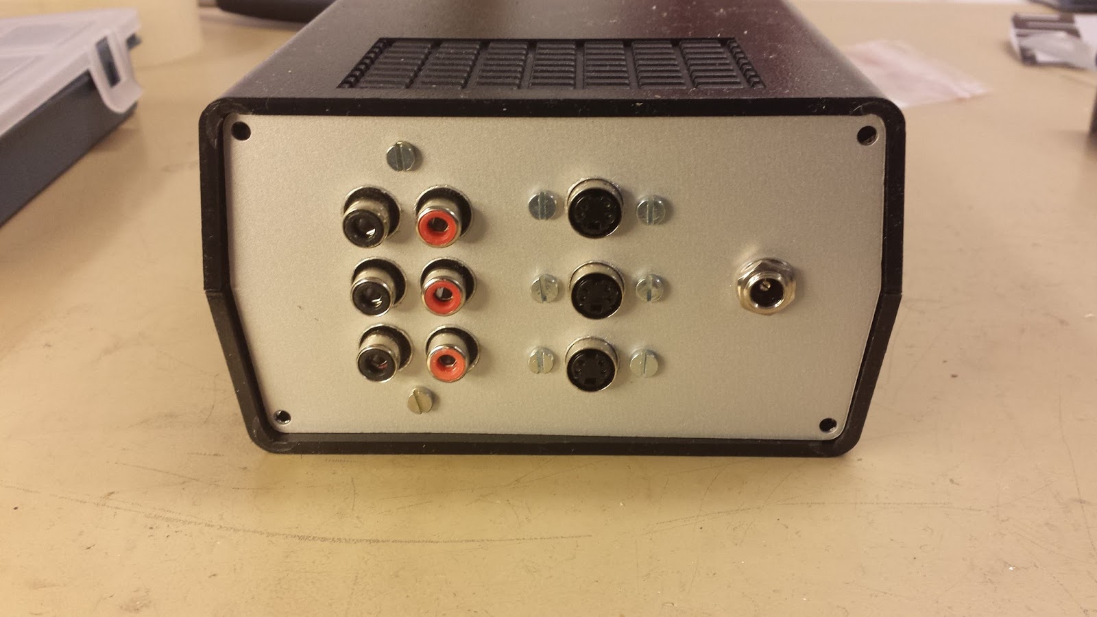
And the connectors mounted. This will be the rear side of the housing. The front will have ony one button for canceling the track currently playing. This is something i missed when repairing the CD changers. Sometimes it played songs that I didn't like and there was no way to cancel the song and skip to next. The front plate has also to be opened to access the memory card at the MP3 shield, so keeping it clear with as few things as possible makes it easier to reach in and access the card.

This is the first autonomous boot of the MP3 player. Until now I have powered the Arduinos through the USB port connected to a PC. Now the power comes from a power supply connected to the AC outlet of the jukebox amplifier, where the changers used to be connected. The cable turning to the left at the picture are for the serial data connectors. It will connect to an Arduino Mega proto board, but that's still at my todo list.