lördag 26 januari 2013

Dr Who completed

Dr Who is now completed and ready to be picked up.

While I had the time expander disassembled I cleaned and waxed the mini playfield, cleaned the target assembly and polished the ball deflectors and ball guides.
 

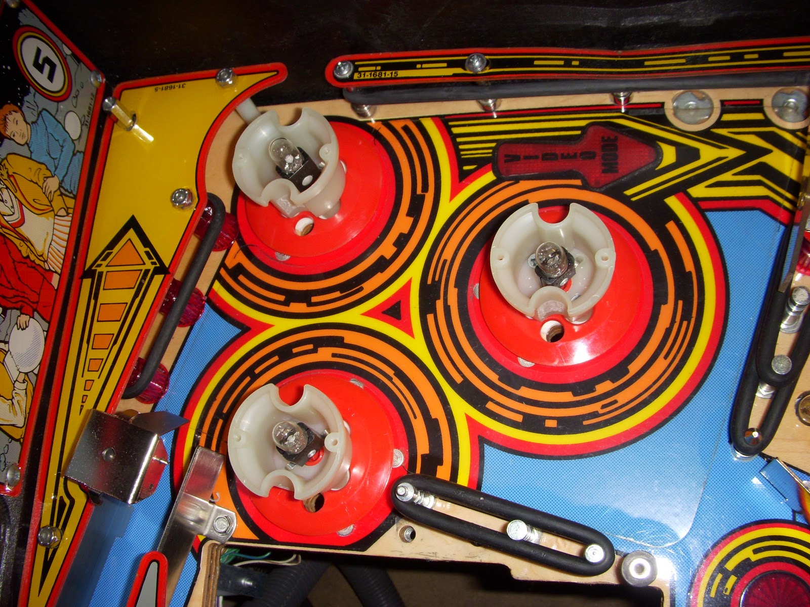
The skirts of all three bumpers were damaged and I changed those. This was an operation of almost four hours. While the bumpers were removed it was easy to clean and polish this part of the playfield. The bumper bodies and bases were cleaned and the rod an rings polished before I put it all back together again.


The blue signal light of the doctors TARDIS was misaligned, I took it apart and put it back as it should be.
 
 
The front of the cabinet had holes drilled for a locking bar, these holes are now covered by flathead bolts. These was chromed from the beginning, but it didn’t look right since the coin door are black and the cabinet is quite dark so I ended up spraying them flat black.
 
 
The batteries are removed from the CPU and put in to an external holder. This is the most important modification to do to a machine. There are a lot of pinballs out there who have had their CPU’s damaged by leaking batteries. 

On top of this the playfield are cleaned and polished, the cabinet vacuumed from scrap and dirt, the coin box, flipper buttons and playfield glass cleaned. All plastic ramps was cleaned and polished while out of the playfield, including the one at the underside guiding the balls from the time expander to the VUK. There was a lot of broken lamps and flashers ( 29 * #555, 4 * #42 and 6 * 906) most of the broken 555’s sat in the backbox. A GI fuse for the backbox was also blown (F110), so there was not much light in it from the beginning. There was some scrap between the translite and glass which I removed.
All in all it was about 25 hours of well spent labor.


fredag 25 januari 2013

Dr Who time expander


This unit turned out to be a real troublesome. I have worked hours with it and I’m now convinced that I can’t do anything about the problem.


This is the elevation mechanism. It consists of a support bracket in which the main bracket slides up and down. The movement is controlled by a rotating cam disc. In this picture it is elevated a bit past its top position. The two brackets are joined together by four rollers, two in the top fixed at the support bracket and two rollers at the bottom of the main bracket. While the main bracket is in the down or mid position it is stable but in the top position where the upper and lower rollers are near each other the main bracket gets unstable. I first tried to add an adjustable stop for the top position of the main bracket, it’s the rubber in the top left in the picture. The thought was that it should prevent the main bracket from tilting to the left. It didn’t work, the tilting occurs just before the main bracket reaches its top position. Without the stop it tilts and stays in that position, with the stop it tilts and then it is brought back in the horizontal position, it looked worse with the stop than without it so I removed it. It is possible to adjust the width of the support bracket a little bit by an adjustment plate at the backside of the mechanism. If it is widened a bit it firms the rollers and the main bracket gets more stable in the top position. This worked good for a while but suddenly the mechanism jammed and this caused the gearbox to break, the soldering of the gear at the outgoing axle broke. Luckily it happened while I still had the game at the workshop. A friend of mine who works at a mechanic workshop helped me to solder the gear back on the axle using silver solder. After this I adjusted the support bracket back to the original position and gave up. If anyone has a solution for this problem, please let me know.

The gear and axle before and after repair