söndag 12 januari 2014

And then there was light

Just a short note to say that the G.I. connectors at the driver board have been changed and G.I. is now working as it should. While taking out the driver board I found another connector that needed attention, J106 was soldered directly to the male connector. I gave it a new set of connectors to be able to take the board out without soldering.
 
 I also found a problem with the speaker cables. At some point in time they have been cut off. Probably to get the display panel out of the game, without the effort of disentangle the speaker cable all the way up to the connector. It was reconnected and insulated with tape, but tape ages and now one of the cables was uninsulated and could have been shorted in to anything at the driver board, probably causing major problems. I reinsulated the cables with shrink tubing.

tisdag 7 januari 2014

Missing G.I.


I was planning to start the disassembly of the playfield today to prepare it for cleaning and change of rubbers. But before I started I found another problem, the lower half of the playfield is missing the G.I. I hadn’t noticed this before and I do not think the owner had either. I had a look at the fault and the cause is a fried connector at the power driver board. Both the male and female connectors have to be changed. Also the connector above seems to have been a bit hot, so I will change that one as well to make sure it does not cause any problems. Unfortunately I’m out of 11 pin females for the moment so I have to order a couple before I can fix it.
 
This was the first time I opened up the backbox and I found a surprise in it, check the upper left fuse, F108, at the picture below. Somebody didn't have a spare fuse and instead shorted it by a wire. Never ever do anything like this, the fuses are there for a reason and should always be replaced with a fuse of the proper amperage.


måndag 6 januari 2014

The Sanctum brick wall

The Sanctum brick wall is now sorted. I took it apart and cleaned and polished the parts and replaced the coil sleeve and the broken spring. The lifting mechanism does now fall back down by its own weight, as it should. The reason for the sluggish movement of the lifting mechanism seems to have been caused by someone fiddling with it and causing the plunger to not line up properly with the coil.  
 
 
The Switch that should indicate that the target is down was misaligned. As it was bent it would have been triggered by the lifting mechanism dropping down after lifting the target instead of being triggered by a dropped target. This didn’t happen since the lifting mech didn’t fall back down as it should. But once that problem was fixed also the Switch had to be realigned to be triggered by the target only.

 
I have played the game for about 30-40 minutes and the ball lock magnet and brick wall are now working as it should.


tisdag 31 december 2013

Two new projects

A couple of days after Christmas I got two new projects in to the workshop. A Williams Flash and a Bally The Shadow. They are both working but in need of service.

 
I started with The Shadow and it has several issues.
Left flipper does sometime not drop back when releasing the flipper button.
Right flipper sometimes fold back when catching a high velocity ball.
The sanctum magnet does not catch the ball.
Upper right diverter does sometime not flip over when pressing the button.
Some switches seem not to work, there are several switches to check in the error report.

 
The left picture is the left flipper assembly and it have probably had problems before, check the way the return spring have been tensioned by winding it round the tab of the flipper base. The right picture is the right flipper assembly and it is currently locked against the EOS switch, just a light tap at the switch release the crank. Here you also can see the reason why the flipper folds back when catching a ball, one cable of the EOS switch is loose. I'll order a flipper rebuild kit to sort out the flipper issues.   
 
The sanctum magnet works as it should in test mode but the problem seems instead to be related to the brick wall drop target located behind the magnet. There is a spring in the lower right corner that should retract the target when released by the solenoid, but the spring is broken. Also the pivot arm that raises the drop target are very sluggish and does not allow the target to go all the way down and close the switch. it feels like the plunger does not move free in the coil sleeve. I have to take this assembly out of the game and inspect it to find out the cause of the problem. I do also need a new spring to get it to work properly.
 
 
The left picture is the left ramp diverter, which works properly. I just added the picture it to show that there has been quite a lot of fiddling with the springs in this machine. The right picture is the right diverter which sometimes faile to switch over. As you can see we have a spring issue also here, it has been mounted upside down causing the spring to slide against the armature. This might be the cause of the diverter not moving, but I'm not sure. I'll order a couple of new springs for these two assemblies and make sure they are properly installed and see if it solves the problem.


söndag 8 september 2013

Pioneer CJ-V50 and PD-MV55

I have been doing some work with the CJ-V50 MP3 player project during the summer vacation.

First part of the project was to emulate the CD changers using an Arduino. I choose the Mega version since it have four serial ports and I need three to emulate the three original CD changers. After some fiddling with the software I got this part working, but for now only emulating one CD changer.
The next step was to get a MP3 player shield up and running.  Originally I planned to use the Rough robotics rMP3 shield. But it’s quite hard to find it, there is no reseller in Sweden, closest one I have found is in Denmark. Instead I went for the Sparkfun MP3 player shield. I started experimenting with the MP3 shield using an Arduino Uno and got it up and running quite quick thanks to all code and examples available at the Internet, then I transferred the code and shield over to the Mega and got some problems until I realized that the Mega doesn’t have the SPI bus at the same pins as the Uno. When knowing that it was easy to get the MP3 shield to work also at the Mega.

Next step was to combine the CD changer emulator software with the MP3 player software, and now I run in to problems. The software needed to feed the MP3 player with data from the SD card through the Arduino doesn’t leave much processor power for other processes. So when playing a track there wasn’t enough free processor time to also keep up the communication to the jukebox controller. I think the rMP3 shield would have been a better option since, as far as I know,  it has an onboard processor for streaming the data from the SD card to the MP3 player chip and thus release the Arduino from that task. But I would like to stick to the Sparkfun shield since it is easier to find. The solution for my problem was to use two Arduinos, one Uno for the MP3 player shield and a Mega for the CD changer emulation. These two communicate through the I2C bus.

The litle green module to the left, on top of the MP3 player shield, is a DC filter removing the DC component of the output signal before feeding it to the amplifier.

I have made a short video of my first tests where the player are playing some short MP3 R2D2 bleeps, to verify that the tracks was changed according to the commands sent by the jukebox controller: http://www.youtube.com/watch?v=jRsjSJzB6qw
 
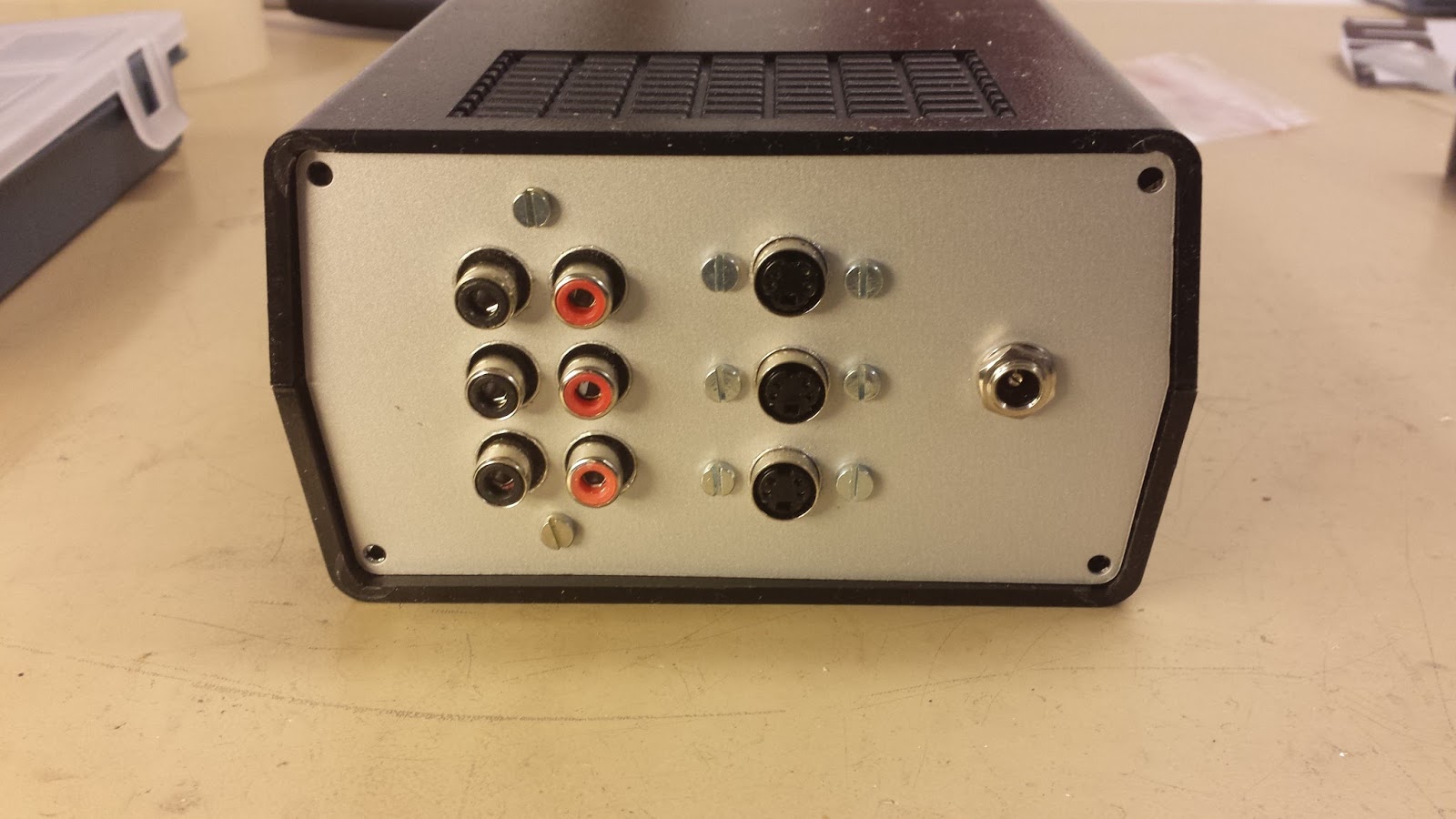
These are the connectors needed, power, three 4-pin mini DIN for the serial busses and three pair of audio connectors.

Holes drilled
 
And the connectors mounted. This will be the rear side of the housing. The front will have ony one button for canceling the track currently playing. This is something i missed when repairing the CD changers. Sometimes it played songs that I didn't like and there was no way to cancel the song and skip to next. The front plate has also to be opened to access the memory card at the MP3 shield, so keeping it clear with as few things as possible makes it easier to reach in and access the card.


This is the first autonomous boot of the MP3 player. Until now I have powered the Arduinos through the USB port connected to a PC. Now the power comes from a power supply connected to the AC outlet of the jukebox amplifier, where the changers used to be connected. The cable turning to the left at the picture are for the serial data connectors. It will connect to an Arduino Mega proto board, but that's still at my todo list.

torsdag 8 augusti 2013

Stern Sharkey’s shootout


This machine isn’t ready yet. I have cleaned the CPU board from the battery residues. To be able to get it clean I had to remove U202 and U216 and I put new IC’s back in sockets. Also the socket for the U213 PAL IC was damaged and exchanged, even the pins of the PAL was green. But the main cause for the board no to boot was probably the reset button. Now the CPU boots and it is possible to play the game, except for some solenoids that does not work. But the display is completely black. The Display driver board had got some dripping from the battery as well, but just in the corner round U20. I removed the U20, cleaned and put back a new IC in a socket, but it didn’t change anything.
 

I talked to the owner and the cause for the game to be put in storage a couple of years ago (with the batteries still in the holder) was that it smelt burnt and solenoids stopped working. At that time the display worked as it should and because of that I’m quite sure the display and driver are OK and the problem are still at the CPU board. Both the PAL and U202 are involved in driving the display, so the problem is most likely at the CPU board. Yesterday I found a broken trace between U213 pin 11 and U202 pin 13 but repairing it did not solve the problem. One thing that’s makes the fault finding a bit troublesome is that there are no documentation available about the PAL, it’s just a black box and I do not know anything about the logic inside. 

The burnt smell and non-working solenoids was caused by a transistor at the solenoid expander board. It was once an easy fix to get the game going again but now… Do always remove the batteries when storing a game, and do always move the batteries to an external battery holder when working with a game. It’s the single most important thing to do to keep a game alive for the future.

Sega Baywatch


The Baywatch was ready and delivered quite a long time ago, I just haven’t had time to update the blog. The switch I ordered for the ball through solved the two problems of ejecting two balls and not detecting a drained ball. Besides that it was more or less just to tightening some loose nuts, adjusting the left in lane switch and cleaning and a polish of the playfield. I played the game for a long time and all worked fine, until I noticed that the upper right ball gate sometime didn’t open as it should. The cause turned out to be loose screws at the actuator arm. The only problem is that almost the whole playfield have to be disassembled to reach in to the gate, it took almost three hours disassembling, tightening the screws and assemble the lot again.